CNC machining chatter, warpage, and premature tool wear are the three problems that turn a good program into a scrap pile. They are linked: unstable cutting raises vibration, vibration loads the tool and the workpiece, and the part distorts as it releases from the fixture. This guide covers what causes each one and how to control it, including how 2026 edge computing and digital twin tooling are moving chatter detection upstream of the machine.
1. Managing chatter: controlling unwanted vibration
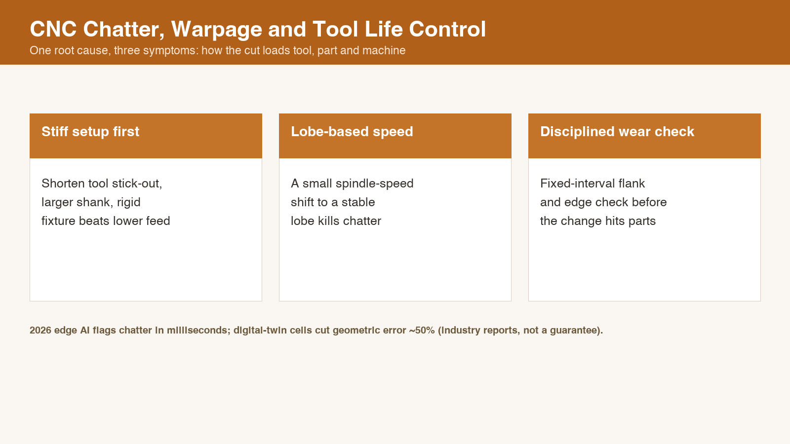
Chatter is a self exciting vibration between the tool, the workpiece, and the machine structure. It leaves a telltale wavy finish and, left alone, breaks tooling and ruins surface quality. The practical control is the stability lobe diagram: for a given depth of cut and tool, there is a spindle speed where the system stays stable and speeds where it does not. Moving the spindle speed by a modest amount often kills chatter without changing anything else.
Other levers are stiffness and overhang. Shorten the tool stick out, use a larger diameter shank, and stiffen the setup before you reduce the feed. A flexible setup will chatter at depths a rigid one absorbs. Our five axis CNC guide covers how orientation and access change the effective stiffness of a cut.
2. Preventing machining induced distortion: residual stress
Warpage shows up after the part is cut free, when locked in residual stress relaxes. It is most severe on thin walls and on parts where roughing removed a lot of material from one side. The fix is to balance the stock removal and to leave a uniform finish allowance so the final pass takes a consistent cut from a symmetric blank.
For tight tolerance work, stress relief before finish machining, and sometimes between roughing and finishing, pays for itself in held dimensions. The point is to let the distortion happen where you can still cut it back out, not after the last pass. Tied to this, datum selection decides which faces the part is referenced from, which matters once the part starts to move.
3. Extending tool life: thermal and mechanical load
Tool life is governed by heat and by the mechanical load at the cutting edge. Heat comes from speed and from insufficient coolant or wrong coating; mechanical load comes from depth, feed, and interrupted cuts. The cheapest tool life gain is usually feed and speed tuning against the material, not a more expensive insert.
Watch the wear mode. Flank wear shortens dimension control, edge chipping causes roughness spikes, and built up edge changes the geometry mid run. A simple wear check at a fixed interval catches the change before it reaches the part. Clean chips and controlled deburring matter here too, because abrasive swarf recut by the tool accelerates wear; our deburring and cleaning guide explains why.
4. In 2026: AI and digital twins move chatter control upstream
The newer development is not a better insert, it is better sensing and modelling. Edge AI running on the machine controller now distinguishes normal cutting chatter from a dangerous tool path deviation within milliseconds, and it can slow the feed or alert the operator before damage occurs. That capability matters most on unattended shifts where no one is standing by the machine.
A 2026 industrial report documented digital twin deployments at a UK tier one supplier cutting geometric and thermal error roughly in half on a five axis machining centre, with the saving coming from virtual proving of NC code plus live compensation rather than faster spindles. The US NIST published a CNC digital twin build reference in December 2024 framed against the ISO 23247 manufacturing digital twin standard, which gives the architecture a common data schema. Academic work in 2026 reached above 95 percent recall on physics informed chatter detection for thin walled turning.
These are vendor, industry, and academic results, not Sureton production claims. We mention them so buyers understand that chatter and tool life are now engineering problems with data backed solutions, not just operator feel. The shop floor reality is still the lobe diagram, the rigid setup, and the disciplined wear check; the new tooling makes those easier to apply consistently.
5. Summary: engineer the process, not just the part
Chatter, warpage, and tool wear are symptoms of how the cut interacts with the machine and the blank. Control them with the stability lobe chart, a stiff and short setup, balanced stock removal, and disciplined wear checks, and add sensing where unattended runs demand it. For parts that also need verified surface quality, our surface roughness guide and our medical CNC guide show how the controls stack up. Send us the drawing and we will tell you which of these three is the one most likely to bite on your part.
Related guides in this topic
Authoritative references
Independent third-party standards and industry bodies, provided for further reading. Sureton is not responsible for third-party content.